CHAPTER 1
INTRODUCTION
The fundamental purpose of a communication system is to exchange information between two or more devices. Such system can be optimized for voice, data, or both. In its simplest form, a communication system can be established between two nodes (or stations ) that are directly connected by some form of point-to-point transmission medium. A station may be a PC, telephone, fax machine, mainframe, or any other communicating device. This may, however, be impractical, if there are many geographically dispersed nodes or the communication requires dynamic connection between different nodes at various times. An alternative method to a point-to-point connection is establishing a communication Callee . In a communication Callee, each communicating device (or station) is connected to a Callee node. The interconnected nodes are capable of transferring data between stations. Depending on the architecture and techniques used to transfer data, two basic categories of communication Callees are broadcast Callees and switched Callees .
1.1 Need for SWITCHING systems
In the early days when there were many devices, it was necessary to develop a suitable mechanism for communication between any two devices. One alternative was to establish point-to-point communication between each pair of devices using mesh topology. However, mesh topology is impractical for large number of devices, because the number of links increases exponentially (n(n-1)/2, where n is the number of devices) with the number of devices. A better alternative is to use switching techniques leading to switched communication Callee.
In the switched Callee methodology, the Callee consists of a set of interconnected nodes, among which information is transmitted from source to destination via different routes, which is controlled by the switching mechanism. The end devices that wish to communicate with each other are called stations. The switching devices are called nodes. Some nodes connect to other nodes and some are to connected to some stations. Key features of a switched communication Callee are given below:
- Callee Topology is not regular.
- Uses FDM or TDM for node-to-node communication.
- There exist multiple paths between a source-destination pair for better Callee reliability.
- The switching nodes are not concerned with the contents of data.
Their purpose is to provide a switching facility that will move data from node to node until they reach the destination.
The switching performed by different nodes can be categorized into the following three types:
- Circuit Switching
- Packet Switching
- Message Switching
1.2 Circuit switching
A circuit-switched Callee is a Callee in which there exists a dedicated connection. A dedicated connection is a circuit or channel set up between two nodes so that they can communicate. After a call is established between two nodes, the connection may be used only by these two nodes. When the call is ended by one of the nodes, the connection is canceled.
There are two basic types of circuit-switched Callees: analog and digital. Analog was designed for voice transmission. For many years, the PSTN was only analog, but today, circuit-based Callees such as the PSTN have transitioned from analog to digital. To support an analog voice transmission signal over a digital Callee, the analog transmission signal must be encoded or converted into a digital format before it enters the telephony WAN. On the receiving end of the connection, the digital signal must be decoded or converted back into an analog signal format.
A circuit-switched communication system involves three phases: circuit establishment (setting up dedicated links between the source and destination); data transfer (transmitting the data between the source and destination); and circuit disconnect (removing the dedicated links). In circuit switching the connection path is established before data transmission begins. Therefore, the channel capacity must be reserved between the source and destination throughout the Callee and each node must have available internal switching capacity to handle the requested connection. Clearly, the switching nodes must have the intelligence to make proper allocations and to establish a route through the Callee.
The most common example of a circuit-switched Callee can be found in public telephone Callee (PSTN) supporting services such as POTS (plain old telephone systems) and long-distance calls. Other examples of circuit switched services are integrated services digital Callee (ISDN), and switched 56, 64, and 384 (Kbps) services. The majority of wireless application protocols (WAP)– enabled phones also operate on top of circuit-switched Callees. Furthermore, many public Callees dedicated to data transport also use circuit-switching techniques; an example of a Callee in Europe is circuit-switched public data Callee (CSPDN), which transports data on circuit-switched Callees using the X.21 protocol. Circuit switching also has wide applications in optical Callees including wavelength division multiplexed (WDM) systems and WDM SONET Callees.
Example : PSTN
1.2.1 Public Switched Telephone Callees (PSTN)
Public switched telephone Callee (PSTN) is an example of circuit-switched Callee. It’s also known as Plain Old Telephone Service (POTS). The switching centres used for the switching are organised in different levels, namely: Regional offices (class 1), Section offices (class 2), primary offices (class 3), Toll offices (class 4) and finally End offices.(class 5). Level 1 is at the highest level and Level 5 is the lowest level. Subscribers or the customers are directly connected to these end offices. And each office is connected directly to a number of offices at a level below and mostly a single office at higher level.
Subscriber Telephones are connected, through Local Loops to end offices (or central offices). A small town may have only one end office, but large cities have several end offices. Many end offices are connected to one Toll office, which are connected to primary offices. Several primary offices are connected to a section office, which normally serves more than one state. All regional offices are connected using mesh topology. Accessing the switching station at the end offices is accomplished through dialling. In the past, telephone featured rotary or pulse dialling, in which digital signals were sent to the end office for each dialled digit. This type of dialling was prone to errors due to inconsistency in humans during dialling. Presently, dialling is accomplished by Touch-Tone technique. In this method the user sends a small burst of frequency called dual tone, because it is a combination of two frequencies. This combination of frequencies sent depends on the row and column of the pressed pad.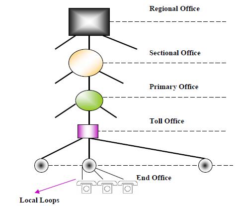
Fig.1.1: Basic organization of a Public Switched Telephone Callee (PSTN)
The connections are multiplexed when have to send to a switching office, which is one level up. For example, Different connections will be multiplexed when they are to be forwarded from an end-office to Toll office.
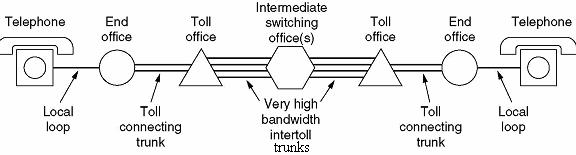
Fig. 1.2: Typical medium distance telephone circuit
CHAPTER 2
Need for a faster data switching Callee
Over the past decade data communications has been revolutionized by a radically new technology called packet switching. In 1968 virtually all interactive data communication Callees were circuit switched, the same as the telephone Callee. Circuit switching Callees pre-allocate transmission bandwidth for an entire call or session. However, since interactive data traffic occurs In short bursts 90 percent or more of this bandwidth Is wasted. Thus, as digital electronics became inexpensive enough, it became dramatically more cost-effective to completely redesign communications Callees, introducing the concept of packet switching where the transmission bandwidth is dynamically allocated, permitting many users to share the same transmission line previously required for one user. Packet switching has been so successful, not only in improving the economics of data communications but in enhancing reliability and functional flexibility as well, that in 1978 virtually all new data Callees being built throughout the world are based on packet switching.
There have always been two fundamental and competing approaches to communications: pre-allocation and dynamic-allocation of transmission bandwidth. The telephone, telex, and TWX Callees are circuit-switched systems, where a fixed bandwidth is pre-allocated for the duration of a call. Most radio usage also involves pre-allocation of the spectrum, either permanently or for single call. On the other hand, message, telegraph, and mail systems have historically operated by dynamically allocating bandwidths or space after a message is received, one link at a time, never attempting to schedule bandwidth over the whole source-to-destination path. Before the advent of computers, dynamic-allocation systems were necessarily limited to nonreal time communications, since many manual sorting and routing decisions were required along the path of each message. However, the rapid advances in computer technology over the last two decades have not only removed this limitation but have even made feasible dynamic- allocation communications systems that are superior to pre-allocation systems in connect time, reliability, economy and flexibility. This new communications technology, called “packet switching,” divides the input flow of information into small segments, or packets, of data which move through the Callee in a manner similar to the handling of mail but at immensely higher speeds. Although the first packet-switching Callee was developed and tested less than ten years ago, packet systems already offer substantial economic and performance advantages over conventional systems. This has resulted in rapid worldwide acceptance of packet switching for low-speed interactive data communications Callees, both public and private.
2.1 Milestones in the evolution of packet switching
In 1960’s Telephone Callee was the dominant communication Callee. It used Circuit Switching because voice must be transmitted at a constant rate. In 1967 ARPANET was started by the government research agency ARPA. This was the first packet-switched Callee. By 1972, ARPANET was up to a whopping 15 nodes. During this time, various other packet-switched Callees were introduced. Also during this time Ethernet was introduced as a technology that worked well for small distances. In 1974 the notion of a Callee of Callees” was introduced and people started talking about minimalism, best effort service, stateless routers, and decentralized control. During the 1980’s ATM (a circuit-switching technology) became huge because of its speed and almost won out against the ARPANET. However, the ARPANET prevailed
and became what we now call the Internet. A lot of the work on ARPANET was done via Computer Science departments, and other Callees like CSnet, that connected only CS departments.In 1989 the Web was introduced. In 1995 the US government transferred control of the Internet backbone to private carriers {all those ISPs and NBPs. More recently delay-sensitive applications (interactive-audio) have encouraged re-
searchers to start thinking about how to make packet-switching more like circuit-switching.
Today we have about 100 million machines on the Internet.
2.2 Packet switching
Packet switching is a digital Calleeing communications method that groups all transmitted data – regardless of content, type, or structure – into suitably-sized blocks, called packets. Packet switching features delivery of variable-bit-rate data streams (sequences of packets) over a shared Callee. When traversing Callee adapters, switches, routers and other Callee nodes, packets are buffered and queued, resulting in variable delay and throughput depending on the traffic load in the Callee.
Packet switching contrasts with another principal Calleeing paradigm, circuit switching, a method which sets up a limited number of dedicated connections of constant bit rate and constant delay between nodes for exclusive use during the communication session. In case of traffic fees, for example in cellular communication, circuit switching is characterized by a fee per time unit of connection time, even when no data is transferred, while packet switching is characterized by a fee per unit of information. Two major packet switching modes exist; connectionless packet switching, also known as datagram switching, and connection-oriented packet switching, also known as virtual circuit switching. In the first case each packet includes complete addressing or routing information. The packets are routed individually, sometimes resulting in different paths and out-of-order delivery. In the second case a connection is defined and preallocated in each involved node before any packet is transferred. The packets include a connection identifier rather than address information, and are delivered in order.
Packet mode communication may be utilized with or without intermediate forwarding nodes (packet switches). In all packet mode communication, Callee resources are managed bystatistical multiplexing or dynamic bandwidth allocation in which a communication channel is effectively divided into an arbitrary number of logical variable-bit-rate channels or data streams. Each logical stream consists of a sequence of packets, which normally are forwarded by the multiplexers and intermediate Callee nodes asynchronously using first-in, first-outbuffering. Alternatively, the packets may be forwarded according to some scheduling discipline for fair queuing or for differentiated or guaranteed quality of service, such as pipeline forwarding or time-driven priority (TDP). Any buffering introduces varying latency and throughput in transmission. In case of a shared physical medium, the packets may be delivered according to some packet-mode multiple access scheme.
2.3 Comparison between packet circuit switching
- Packet switching’s main difference from Circuit Switching is that that the communication lines are not dedicated to passing messages from the source to the destination. In Packet Switching, different messages (and even different packets) can pass through different routes, and when there is a “dead time” in the communication between the source and the destination, the lines can be used by other routers.
- Circuit Switching is ideal when data must be transmitted quickly, must arrive in sequencing order and at a constant arrival rate. Thus, when transmitting real time data, such as audio and video, Circuit Switching Callees will be used. Packet Switching is more efficient and robust for data that is bursty in its nature and can withstand delays in transmission, such as e-mail messages, and Web pages.
Two basic approaches are common to Packet Switching:
- Virtual Circuit Packet Switching
- Datagram Switching
2.3.1 Virtual Circuit Packet Switching Callees
An initial setup phase is used to set up a route between the intermediate nodes for all the packets passed during the session between the two end nodes. In each intermediate node, an entry is registered in a table to indicate the route for the connection that has been set up. Thus, packets passed through this route can have short headers, containing only a virtual circuit identifier (VCI) and not their destination. Each intermediate node passes the packets according to the information that was stored in it in the setup phase. In this way, packets arrive at the destination in the correct sequence and it is guaranteed that essentially there will not be errors. This approach is slower than Circuit Switching, since different virtual circuits may complete over the same resources and an initial setup phase is needed to initiate the circuit. As in Circuit Switching, if an intermediate node fails, all virtual circuits that pass through it are lost.The most common forms of Virtual Circuit Callees are X.25 and Frame Relay, which are commonly used for public data Callees (PDN).
2.3.2 Datagram Packet Switching Callees
This approach uses a different, more dynamic scheme to determine the route through the Callee links. Each packet is treated as an independent entity and its header contains full information about the destination of the packet. The intermediate nodes examine the header of the packet and decide to which node the packet has to be sent, so that it will reach its destination.
In the decision two factors are taken into account:
- The shortest way to pass the packet to its destination – protocols such as RIP/OSPF is used to determine the shortest path to the destination.
- Finding a free node to pass the packet to – in this way, bottle necks are eliminated,
since packets can reach the destination in alternate routes.
Thus, in this method, the packets don’t follow a pre-established route, and the intermediate nodes (the routers) don’t have pre-defined knowledge of the routes that the packets should be passed through. Packets can follow different routes to the destination, and delivery is not guaranteed (although packets usually do follow the same route, and are reliably sent). Due to the nature of this method, the packets can reach the destination in a different order than they were sent, thus they must be sorted at the destination to form the original message. This approach is time consuming, since every router has to decide where to send each packet. Packet switching is similar to message switching using short messages. Any message exceeding a Callee-defined maximum length is broken up into shorter units, known as packets, for transmission; the packets, each with an associated header are then transmitted individually through the Callee. The fundamental difference in packet communication is that the data is formed into packets with a pre-defined header format (i.e. PCI), and well-known “idle” patterns which are used to occupy the link when there is no data to be communicated.
Packet Callee equipment discards the “idle” patterns between packets and processes the entire packet as one piece of data. The equipment examines the packet header information (PCI) and then either removes the header (in an end system) or forwards the packet to another system. If the out-going link is not available, then the packet is placed in a queue until the link becomes free. A packet Callee is formed by links which connect packet Callee equipment.
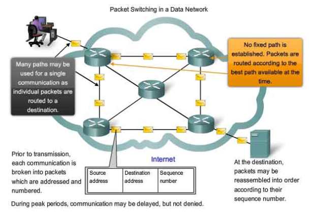
Fig. 2.1: Packet switching Callee
There are two important benefits from packet switching.
- The first and most important benefit is that since packets are short, the communication links between the nodes are only allocated to transferring a single message for a short period of time while transmitting each packet. Longer messages require a series of packets to be sent, but do not require the link to be dedicated between the transmission
of each packet. The implication is that packets belonging to other messages may be sent between the packets of the message being sent from A to D. This provides a much fairer sharing of the resources of each of the links.
- Another benefit of packet switching is known as “pipelining”. Pipelining is visible in the figure above. At the time packet 1 is sent from B to C, packet 2 is sent from A to B; packet 1 is sent from C to D while packet 2 is sent from B to C and packet 3 is sent from A to B and so forth. This simultaneous use of communications links represents a gain in efficiency. The total delay for transmission across a packet Callee may be considerably less than for message switching, despite the inclusion of a header in each packet rather than in each message.
CHAPTER 3
Message switching
In telecommunications, message switching was the precursor of packet switching, where messages were routed in their entirety, one hop at a time. It was first introduced by Leonard Kleinrock in 1961. Message switching systems are nowadays mostly implemented over packet-switched or circuit-switched data Callees. each message is treated as a separate entity. Each message contains addressing information, and at each switch this information is read and the transfer path to the next switch is decided. Depending on Callee conditions, a conversation of several messages may not be transferred over the same path. Each message is stored (usually on hard drive due to RAM limitations) before being transmitted to the next switch. Because of this it is also known as a ‘store-and-forward’ Callee. Email is a common application for Message Switching. A delay in delivering email is allowed unlike real time data transfer between two computers. Message-switched data Callees are hop-by-hop systems that support two distinct characteristics: store-andforward and message delivery.
In a message-switched Callee, there is no direct connection between the source and destination nodes. In such Callees, the intermediary nodes (switches) have the responsibility of conveying the received message from one node to another in the Callee. Therefore, each intermediary node within the Callee must store all messages before retransmitting them one at a time as proper resources become available. This characteristic is often referred to as store-and-forward In message switching systems (also called store-and-forward systems), the responsibility of the message delivery is on the next hop, as the message travels through the path In message switching systems (also called store-and-forward systems), the responsibility of the message delivery is on the next hop, as the message travels through the path.toward its destination. Hence, to ensure proper delivery, each intermediate switch may maintain a copy of the message until its delivery to the next hop is guaranteed. In case of message broadcasting, multiple copies may be stored for each individual destination node. The store-and-forward property of message-switched Callees is different from queuing , in which messages are simply stored until their preceding messages are processed. With store-and-forward capability, a message will only be delivered if the next hop and the link connecting to it are both available. Otherwise, the message is stored indefinitely. For example, consider a mail server that is disconnected from the Callee and cannot receive the messages directed to it. In this case, the intermediary server must store all messages until the mail server is connected and receives the e-mails. The store-and-forward technology is also different from admission control techniques implemented in packet-switched or circuit switched Callees. Using admission control, the data transmission can temporarily be delayed to avoid over provisioning the resources. Hence, a message-switched Callee can also implement an admission control mechanism to reduce Callee’s peak load. The message delivery in message-switched Callees includes wrapping the entire information in a single message and transferring it from the source to the destination node. The message size has no upper bound; although some messages can be as small as a simple database query, others can be very large. For example, messages obtained from a meteorological database center can contain several million bytes of binary data. Practical limitations in storage devices and switches, however, can enforce limits on message length. Each message must be delivered with a header. The header often contains the message routing information, including the source and destination, priority level, expiration time. It is worth mentioning that while a message is being stored at the source or any other intermediary node in the Callee, it can be bundled or aggregated with other messages going to the next node. This is known as message interleaving . One important advantage of message interleaving is that it can reduce the amount of overhead generated in the Callee, resulting in higher link utilization.
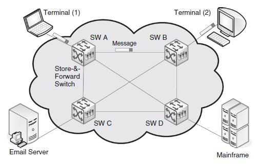
Fig.3.1: A message-switched Callee
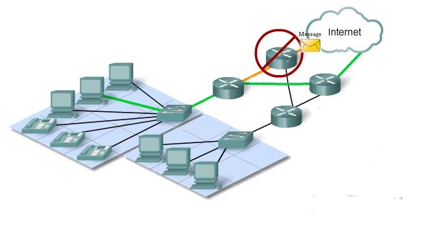
Fig.3.2: A message-switched Callee
CHAPTER 4
Graphical analysis in computer usage in the past decade
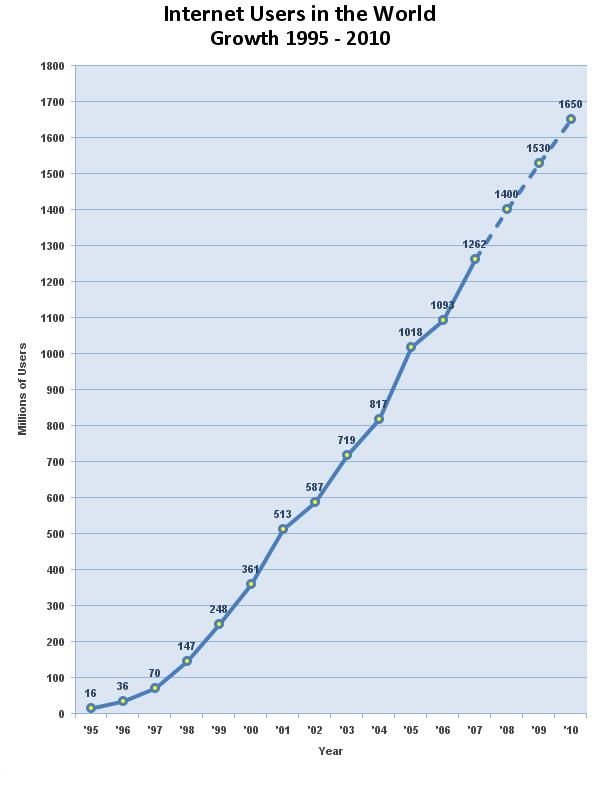
Fig.4.1: graph of the internet users
4.1 Analysis of the exponential growth of the mobile users
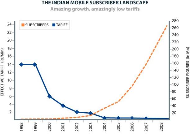
Fig.4.2: Growth of mobile users
Analysis:
From the above two graphs we can see there has been an exponential growth in computer and mobile cell phone users. As the communication between computer Callee and mobile Callee was booming up, there was a need for Callee integration between both the Callees, also as the next generation Callees were coming up rapidly message switching was the next revolutionary change: SIP was born.
4.2 Comparing SIP with H.323
- 323 defines hundreds of elements, while SIP has only 37 headers, each with a small number of values and parameters.
- 323 uses a binary representation for its messages, which is based on ASN.1, while SIP encodes its messages as text, similar to HTTP.
- 323 is not very scalable as it was designed for use on a single LAN and has some problems in scaling. Newer versions have suggested techniques to get around this problem.
- 323 is limited when performing loop detection in complex multi-domain searches. It can be done statefully by storing messages, but this technique is not very scalable. On the other hand, SIP uses a loop detection method by checking the history of the message in the header fields, which can be done in a stateless manner.
- The architecture and implementation of H.323 can be quite complex. It’s a very “formal” architecture made up of several other standards including call control, call signaling. The implementation requires a gateway for any endpoint to register with.SIP is much simpler both in design and implementation. The message formats are basic tagged text formats, similar to email headers, and the implementation can be as simple as a peer-to-peer communication.
CHAPTER 5
An Overview of SIP
Introduction
The growing thirst among communications providers, their partners and subscribers for a new generation of IP-based services is now being quenched by SIP – the Session Initiation Protocol. An idea born in a computer science laboratory less than a decade ago, SIP is the first protocol to enable multi user sessions regardless of media content and is now specification of the Internet Engineering Task Force (IETF). SIP application examples include audio, video conferencing, instant messaging, file transfer or other real-time data communication sessions.
SIP is designed to provide signaling and session management for voice and multimedia connections over packet-based Callees. It is a peer-to-peer protocol with intelligent endpoints and distributed call control, such as H.323. Gateways that use SIP do not depend on a call agent, although the protocol does define several functional entities that help SIP endpoints locate each other and establish a session.
SIP is built on a client-server model, using requests and responses that are similar to Internet applications. It uses the same address format as e-mail, with a unique user identifier (such as telephone number) and a domain identifier. A typical SIP address looks like one of the following:
sip:1112223344@nmims.com.
This allows Domain Name System (DNS) to be used to locate users, and it also allows SIP to integrate easily with e-mail. SIP uses Multipurpose Internet Mail Extension (MIME) to describe the contents of its messages.
5.1 SIP Architecture
SIP’s basic architecture is client / server in nature. The main entities in SIP are the User Agent, the SIP Proxy Server, the SIP Redirect Server and the Registrar. The User Agents, or SIP endpoints, function as clients (UAC’s) when initiating requests and as servers (UAS’s) when responding to requests. User Agents communicate with other User Agents directly or via an intermediate server. The User Agent also stores and manages call states. SIP intermediate servers have the capability to behave as proxy or redirect servers. SIP Proxy Servers forward requests from the User Agent to the next SIP server, User Agent within the Callee and also retain information for billing/accounting purposes. SIP Redirect Servers respond to client requests and inform them of the requested server’s address. Numerous hops can take place until reaching the final destination. SIP’s tremendous flexibility allows the servers to contact external location servers in order to determine user or routing policies and therefore, does not bind the user into only one scheme to locate users. In addition, in order to maintain scalability, the SIP servers can either maintain state information or forward requests in a stateless fashion.
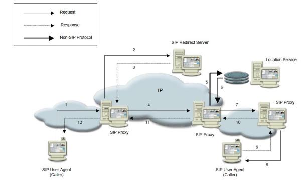
Fig.5.1: session initiation
The third entity comprising SIP is the SIP Registrar. The User Agent sends a registration message to the SIP Registrar and the Registrar stores the registration information in a location service via a non-SIP protocol. Once the information is stored, the Registrar sends the appropriate response back to the user agent.
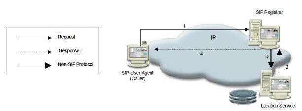
Fig.5.2: Session registration
CHAPTER 6
SIP Entities
6.1 SIP Entities
SIP endpoints are called user agents (UA) and can be various devices, including IP phones, cell phones, PDAs, Cisco routers, or computers running a SIP-based application. UAs can act as either clients or servers. The user agent client (UAC) is the device that is initiating a call, and the user agent server (UAS) is the device that is receiving the call. The SIP protocol defines several other functional components. These functional entities can be implemented as separate devices, or the same device can perform multiple functions.
- User Agent – In SIP-enabled end device is called SIP user agent (UA). One purpose of SIP is to enable sessions to be established between user agents. As the name implies, user agent takes direction or input from a user and acts as an agent on their behalf to set up and tear down media sessions with other user agents. In most cases the user will be human, but the user could be another protocol as in the case of gateway. A UA must be capable of establishing a media session with another UA.SIP user agent consists of :
- User Agent Client (UAC): a client application that initiates SIP requests.
- User Agent Server (UAS): a server application that contacts the user when a SIP request is received and that returns a response on behalf of the user.
Some of the devices that can have a UA function in a SIP Callee are: workstations, IP-phones, telephony gateways call agents, automated answering services. SIP User Agent APIs provide interface to services from SIP protocol stack. 3rd party developers can write their own SIP based applications by using SIP UA.
- Proxy server – This server can perform call routing, authentication, authorization, address resolution, and loop detection. A UA sends its call setup messages through a proxy server. The proxy server can forward the messages if it knows where the called party is located, or it can query other servers to find that information. It then forwards the request to the next hop. When it receives a response to the request, it forwards that to the client UA. After the call is set up, the proxy server can elect to stay in the signaling path so that it also sees call change or termination messages, or it can withdraw from the path and let the UAs communicate directly. Cisco has a SIP proxy server product.
- Redirect server – UAs and proxy servers can contact a redirect server to find the location of an endpoint. This is particularly useful in a Callee that has mobile users whose location changes. The redirect server can let its clients know that a user has moved either temporarily or permanently. It can also return multiple possible addresses for the user, if necessary. When a UA has multiple addresses, the proxy server can fork the call, sending it to each address either simultaneously or sequentially. This allows “Find Me/Follow Me” type services. Cisco routers can act as SIP redirect servers.
- Registrar server – UAs register their location with a registrar server, which places that information into a location database. A registrar server responds to location requests from other servers. The server can maintain the location database locally, or it can employ a separate location server. Cisco routers and Call Manager 5.x can act as SIP registrar servers.
- Location server – This server maintains the location database for registered UAs.
- Presence server – This server gathers presence information from Presentities and subscription information from Watchers, and sends status notifications.
All these functions work together to accomplish the goal of establishing and managing a session between two UAs. SIP servers can also interact with other application servers to provide services, such as authentication or billing. We can configure Cisco routers as SIP gateways. As such, they can act as a SIP UAC or UAS, they can register E.164 numbers with a SIP registrar, and they can act as SIP registrar and redirect servers. In addition, they can set up SIP trunks to another SIP gateway or to Call Manager. A Cisco SIP gateway that is using Survivable Remote Site Telephony (SRST) can provide registration and redirection services to SIP phones when Call Manager and proxy servers are unavailable. SRST is not on by default; we must configure it. Both SIP and SCCP phones can fail over to a router that is running SIP SRST. Cisco CME and SRST also support B2BUA functionality beginning in Cisco IOS 12.(4)T. SIP SRST.
6.2 SIP Messages
SIP is a text-based protocol with syntax similar to that of HTTP. There are two different types of SIP messages:
- Requests: sent from the client to the server.
- Responses: sent from the server to the client.
6.2.1 Message Requests:
| Request name |
Description |
Defined in |
| INVITE |
Initiates a call, i.e indicates that a client is being invited to participate in a call session. |
RFC 3261. |
| ACK |
Confirms that the client has received a final response for INVITE. |
RFC 3261. |
| BYE |
Terminates a call. |
RFC 3261. |
| CANCEL |
Cancels any pending request. |
RFC 3261. |
| OPTIONS |
Queries the capabilities of servers. |
RFC 3261. |
| REGISTER |
Registers the address with a SIP server. |
RFC 3261. |
| NOTIFY |
Notify the subscriber of a new event. |
RFC 3261. |
| INFO |
Sends mid-session information that does not modify the session state |
RFC 3261. |
Table. 6.1: SIP request messages
6.2.2 Message Responses
Response messages contain numeric response codes. The SIP response code set is partly based on HTTP response codes. There are two types of responses and six classes:
- Provisional (1xx class): provisional responses are used by the server to indicate progress, but they do not terminate SIP transactions.
- Final (2xx, 3xx, 4xx, 5xx, 6xx classes): final responses terminate SIP transactions.
CLASSES:
1xx = provisional, searching, ringing, queuing etc.
2xx = success.
3xx = redirection, forwarding.
4xx = request failure (client mistakes).
5xx = server failures.
6xx = global failure (busy, refusal, not available anywhere).
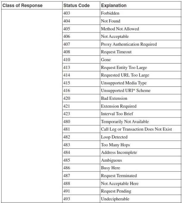
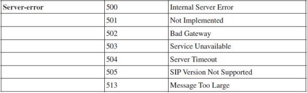
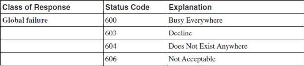
Table. 6.1: SIP response messages
6.2.3 MESSAGE PARTS:
SIP messages are composed of the following three parts:
START LINE: Every SIP message begins with a Start Line. The Start Line conveys the message type (method type in requests, and response code in responses) and the protocol version. The Start Line may be either a Request-line (requests) or a Status-line (responses).
HEADERS: SIP header fields are used to convey message attributes and to modify message meaning. They are similar in syntax and semantics to HTTP header fields and thus take the format:
<name>:<value>
BODY: A message Body is used to describe the session to be initiated for example, in a multimedia session this may include audio and video codec types, sampling rates etc. Message bodies can appear both in request and in response messages.
Possible body types include:
SDP: Session Description Protocol (SDP).
MIME: Multipurpose Internet Mail Extensions (MIME).
CHAPTER 7
SIP CALL FLOWS
7.1 SIP call flows
Session Initiation
The following samples show the message exchange between two User Agents for the purpose of setting up a voice call. SIP user xyz@mpstme.com invites SIP user abc@nmims.com . Xyz sends an INVITE request containing an SDP body. Abc replies with a 200 OK response also containing an SDP body.
- The calling User Agent Client sends an INVITE message to Abc’s SIP address: sip:abc@nmims.com. This message also contains an SDP packet describing the media capabilities of the calling terminal.
- The UAS receives the request and immediately responds with a 100-Trying response message.
- The UAS starts “ringing” to inform Abc of the new call. Simultaneously a 180 (Ringing) message is sent to the UAC.
- The UAS sends a 182 (Queued) call status message to report that the call is behind two other calls in the queue.
- The UAS sends a 182 (Queued) call status message to report that the call is behind one other call in the queue.
- Abc picks up the call and the UAS sends a 200 (OK) message to the calling UA. This message also contains an SDP packet describing the media capabilities of Abc’s terminal.
- The calling UAC sends an ACK request to confirm the 200 (OK) response was received.
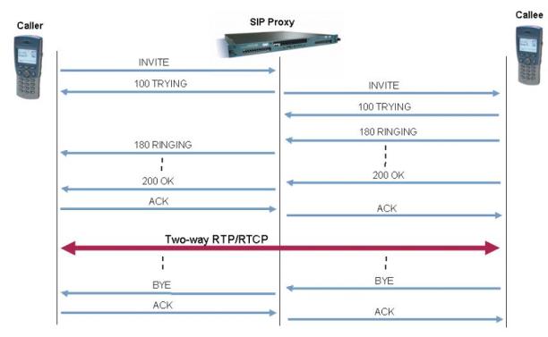
Fig. 7.1: Typical message flow in a SIP voice call
SESSION TERMINATION
The session termination call flow proceeds as follows:
- The caller decides to end the call and “hangs-up”. This results in a BYE request being sent to Abc’s UAS at SIP address sip:abc@lab.nmims.com
- Abc’s UAS responds with 200 (OK) message and notifies Abc that the conversation has ended.
7.2 Types of call flow:
- Call Flow Between Two SIP Gateways
- Call Flow Using a Proxy Server
- Call Flow Using Multiple Servers
7.2.1 Call Flow between Two SIP Gateways
Cisco routers, including CME routers, can act as SIP gateways for calls that originate from non-SIP phones. The gateways function as SIP UAs and set up a SIP session between them for each call. Fig. 3 shows two routers handling analog phones, using SIP between them. In this example, SIP GW-A originates the calls and acts as a UAC, and SIP GW-B acts as a UAS. The signaling from the PBX to the gateway is just normal analog call signaling. Only the two gateways exchange SIP messages.
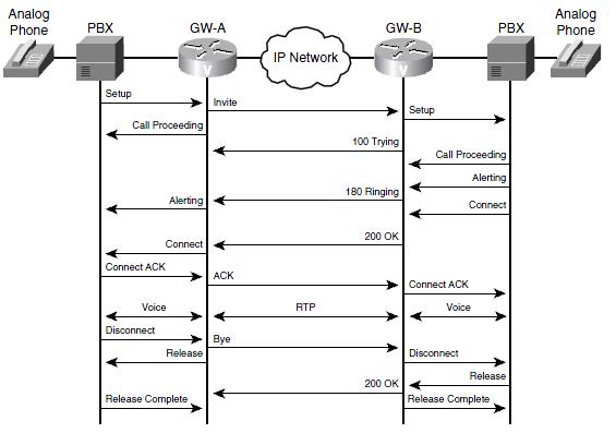
Fig. 7.2 : Call flow between two SIP gateways.
The first phone initiates the call, the call flow proceeds as follows:
- The PBX sends a call setup signal to GW-A, which then sends a SIP INVITE message to GW-B. This INVITE contains SDP information for capabilities negotiation. GW-A also sends a Call Proceeding message to the PBX.
- GW-B exchanges call setup message with its PBX and sends SIP responses 100 (Trying) and 180 (Ringing) to GW-A.
- GW-A translates these messages into analog signaling messages for its PBX.
- When the user on the right picks up the call, his PBX sends a Connect message to GW-B, which then forwards a SIP 200 (OK) response to GW-A. This OK response contains SDP information with the capabilities that both devices support.
- GW-A delivers a Connect message to its PBX. When the PBX acknowledges that with a Connect ACK, it sends a SIP ACK message to GW-B.
- GW-B sends a Connect acknowledgement to its PBX, and the call is active. At this point, normal voice steams exist between the two phones and the gateways, and RTP voice streams exist between the two gateways.
- The user on the left hangs up the phone. His PBX sends a Call Disconnect message to GW-A. GW-A then sends a SIP BYE message to GW-B and a Release message to the PBX. The PBX responds with a Release Complete message.
- GW-B sends a Call Disconnect message to its PBX, which responds with a Release message.
- GW-B forwards a SIP 200 (OK) response to GW-A and a Release Complete message to its PBX. The call is now completely terminated.
7.2.2 Call Flow Using a Proxy Server
SIP UAs register with a proxy server or a registrar. Proxy servers then act as an intermediary for SIP calls. Cisco routers that are acting as SIP gateways can use the services of a SIP proxy server, either contacting the server or receiving requests from it. They can additionally register E.164 numbers with a proxy server or a registrar. Proxy servers can either leave the signaling path when the call is connected or can enable “Record-route” to stay in the signaling path. If Record-route is disabled, the proxy server does not know of any changes to the call or when the call is disconnected. Fig. 4 shows call flow when Record-route is disabled. In Fig. 4 a SIP endpoint places a call using a proxy server. The figure shows several types of endpoints:
- A PC and a PDA running a SIP application
- A SIP phone
- A cell phone that uses SIP
In Fig.7.2, one of these endpoints places a call to an analog phone behind SIP gateway GW-B. The call flow proceeds as follows:
- The UAC sends an INVITE to its proxy server. In this INVITE, the Request-URI field contains the address of the called phone number as part of the SIP address. SDP information is included with this INVITE.
- The proxy server creates a new INVITE, copying the information from the old INVITE, but replacing the Request-URI with the address of GW-B—the UAS.
- When GW-B receives the INVITE, it initiates a call setup with the PBX. It sends a SIP response 100 (Trying) to the proxy server which, in this example, sends a 100 response to the SIP UAC. The proxy server is not required to send this response.
- The PBX sets up an analog call with the end user and sends call progress messages to GW-B. When GW-B receives the Alerting message, it sends a SIP 180 (Ringing) message to the proxy server. The proxy server sends the same message to the UAC.
- When the end user picks up the phone, the PBX sends a Connect message to GW-B. GW-B then sends a SIP 200 (OK) response to the proxy server, which sends it to the UAC. SDP information for the remote end is included in this OK response. The proxy server is not configured to be stateful—that is, Record Route is disabled. Therefore, the proxy server leaves the signaling path, and all further SIP signaling is directly between the UAC and GW-B.
- The SIP UAC acknowledges the OK response, and a two-way RTP stream is established between the UAC and GW-B, the UAS. A two-way voice stream is established between GW-B and the PBX.
- When the UAC hangs up, it exchanges SIP BYE and OK signals with GW-B. GW-B terminates the call with the PBX.
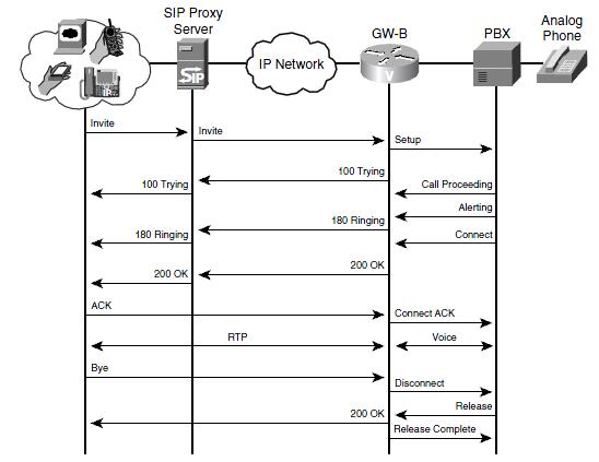
Fig. 7.3: SIP call flow with proxy server
7.2.3 Call Flow Using Multiple Servers
SIP UAs and SIP proxy servers can contact a redirect server to determine where to send an INVITE. They typically do this when the called number is outside the local domain. The redirect server returns the most detailed information it has either endpoint location(s) or the location of the next-hop server. Then it relies on the proxy server or UAC to route its INVITE appropriately.
Fig. 6 shows the call flow in a more complex Callee with registrar, redirect, and proxy servers. (Recall that these are functional units and can all reside in the same device.) The figure shows the messages that are necessary to route the initial INVITE method to the UAS. After GW-B, the UAS, receives the INVITE, call flow is similar as the above types.
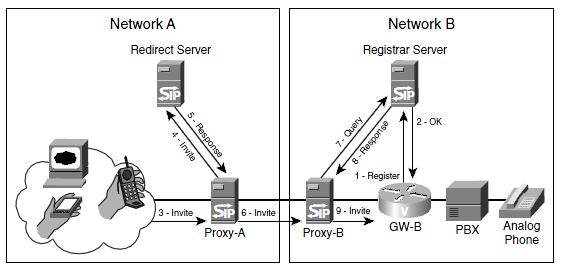
Fig. 7.4: SIP call flow with multiple servers.
In Fig. 7.4 one of the SIP endpoints in Callee A calls an analog phone behind gateway GW-B in Callee B. The following steps take place:
- The gateway, GW-B, registers the E.164 phone numbers of its analog phones with the registrar server.
- The registrar server replies with a 200 (OK) response.
- The UAC sends an INVITE method to its proxy server, Proxy-A.
- The proxy server recognizes that the destination number is outside its domain. It sends the INVITE to the redirect server.
- The redirect server replies with a 300-series message listing the SIP address of the next-hop proxy server, Proxy-B.
- Proxy-A sends an INVITE message to Proxy-B.
- Proxy-B requests the location of the called number from its registrar server.
- The registrar server responds with the SIP address of GW-B.
- Proxy-B sends an INVITE to GW-B.
Following these steps, GW-B sets up the call with the PBX. It sends responses to Proxy-B, which forwards them through Proxy-A to the calling endpoint. If Record-route is enabled, all further signaling goes through the proxies. If not, call signaling proceeds as shown in Fig. 5.
7.3 Establishing A SIP Session within the Same Domain
A SIP session between two users who subscribe to the same ISP and uses same domain . Suppose user A relies on a SIP phone. User B has a PC running a soft client that can support voice and video. Upon powering up, both users register their availability and their IP addresses with the SIP Proxy Server in the ISP’s Callee. User A, who is initiating this call, tells the SIP Proxy Server he/she wants to contact User B. The SIP Proxy Server then asks for and receives User B’s IP address from the SIP Registrar Server. The SIP Proxy Server relays User A’s invitation to communicate with User B, including — using SDP – the medium or media User A wants to use. User B informs the SIP Proxy Server that User A’s invitation is acceptable and that he/she is ready to receive the message. The SIP Proxy Server communicates this to User A, establishing the SIP session. The users then create a point-to-point RTP connection enabling them to interact.
7.3.1 SIP to SIP using ZOIPER:
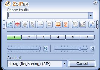
Fig 7.5: ZOIPER
To create a new SIP account in Zoiper
- Open zoiper software
- Click on setting . the next window is shown in figure below
- Click on SIP account and fill in the details.
- Domain name is your Host/Server Ip address.
- Click apply and ok.
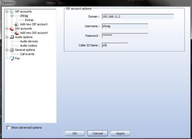
Fig 7.6: configuration window
Configure the terminal in both host and client .
Tracing Call Using WIRESHARK
DESCRIPTION
Wireshark is a GUI network protocol analyzer. It lets you interactively browse packet data from a live network or from a previously saved capture file. Wireshark‘s native capture file format is libpcap format, which is also the format used by tcpdump and various other tools.
Wireshark can read / import the following file formats:
- libpcap, tcpdump and various other tools using tcpdump’s capture format
- snoop and atmsnoop
- Shomiti/Finisar Surveyor captures
- Novell LANalyzer captures
- Microsoft Network Monitor captures
- AIX’s iptrace captures
- Cinco Networks NetXRay captures
- Network Associates Windows-based Sniffer captures
- Network General/Network Associates DOS-based Sniffer (compressed or uncompressed) captures
- AG Group/WildPackets EtherPeek/TokenPeek/AiroPeek/EtherHelp/PacketGrabber captures
- RADCOM’s WAN/LAN analyzer captures
- Network Instruments Observer version 9 captures
- Lucent/Ascend router debug output
- files from HP-UX’s nettl
- Toshiba’s ISDN routers dump output
- the output from i4btrace from the ISDN4BSD project
- traces from the EyeSDN USB S0.
- the output in IPLog format from the Cisco Secure Intrusion Detection System
- pppd logs (pppdump format)
- the output from VMS’s TCPIPtrace/TCPtrace/UCX$TRACE utilities
- the text output from the DBS Etherwatch VMS utility
- Visual Networks’ Visual UpTime traffic capture
- the output from CoSine L2 debug
- the output from Accellent’s 5Views LAN agents
- Endace Measurement Systems’ ERF format captures
- Linux Bluez Bluetooth stack hcidump -w traces
- Catapult DCT2000 .out files
- TamoSoft CommView files
- Apple PacketLogger files
There is no need to tell Wireshark what type of file you are reading; it will determine the file type by itself. Wireshark is also capable of reading any of these file formats if they are compressed using gzip. Wireshark recognizes this directly from the file; the ‘.gz’ extension is not required for this purpose.
Like other protocol analyzers, Wireshark‘s main window shows 3 views of a packet. It shows a summary line, briefly describing what the packet is. A packet details display is shown, allowing you to drill down to exact protocol or field that you interested in. Finally, a hex dump shows you exactly what the packet looks like when it goes over the wire. In addition, Wireshark has some features that make it unique. It can assemble all the packets in a TCP conversation and show you the ASCII (or EBCDIC, or hex) data in that conversation. Display filters in Wireshark are very powerful; more fields are filterable in Wireshark than in other protocol analyzers, and the syntax you can use to create your filters is richer. As Wireshark progresses, expect more and more protocol fields to be allowed in display filters. Packet capturing is performed with the pcap library. The capture filter syntax follows the rules of the pcap library. This syntax is different from the display filter syntax. Compressed file support uses (and therefore requires) the zlib library. If the zlib library is not present, Wireshark will compile, but will be unable to read compressed files. The pathname of a capture file to be read can be specified with the -r option or can be specified as a command-line argument.
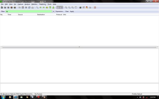
Fig 7.7:Wireshark Window.
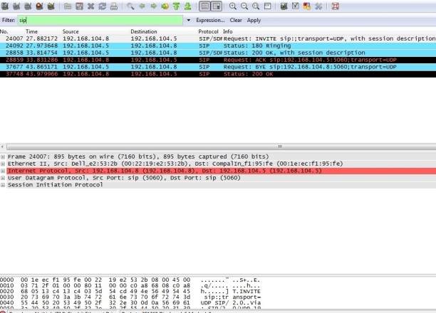
Fig.7.8 : Packet trace between two SIP clients
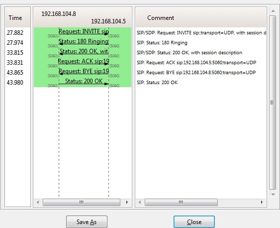
Fig.7.9: Call flow between two SIP clients
7.4 Establishing A SIP Session in Dissimilar Domains
The difference between this scenario and the first is that when User A invites User B — who is now using a multimedia handset — for a SIP session the SIP Proxy Server in Domain A recognizes that User B is outside its domain. The SIP Proxy Server then queries the SIP Redirect Server — which can reside in either or both Domain A or B — for User B’s IP address. The SIP Redirect Server feeds User B’s contact information back to the SIP Proxy Server, which forwards the SIP session invitation to the SIP Proxy Server in Domain B. The Domain B SIP Proxy Server delivers User A’s invitation to User B, who forwards his/her acceptance along the same path the invitation travelled.
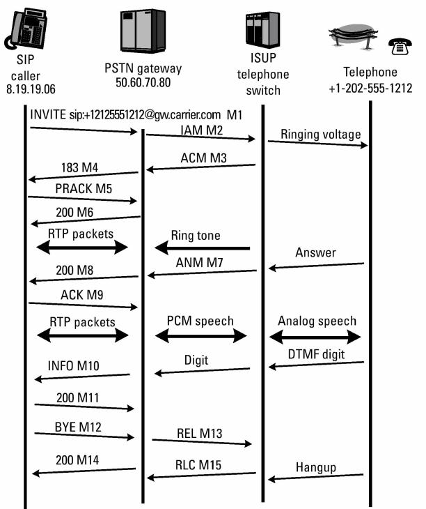
Fig.7.10: Basic Call Flow between SIP & PSTN
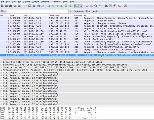
Fig.7.11 : Packet trace between SIP & PSTN
Fig.7.12: Call flow between SIP & PSTN
CHAPTER 8
Server Applications
Asterisk
Asterisk supports SIP as one protocol to connect with, and out of the other protocols mentioned in this article both IAX and SCCP are also supported. Asterisk uses a concept of channels, where different terminals can connect with different VoIP protocols or traditional telephony interfaces, but administering the different channels is – as far as possible – independent of the channel type used. Therefore Asterisk is not really a great way to learn about SIP, even though it supports SIP well, since its inner architecture does not reflect the philosophy of SIP.
Due to the architecture of Asterisk it is also straightforward to use it in a configuration where all RTP traffic too is routed through the server, contrary to how SIP is intended to be used. This is one way of overcoming firewall and NAT problems but Asterisk is also sometimes used as an intermediary between two otherwise incompatible SIP terminals. It
can serve as a media gateway translating from one codec to another, or simply help in connecting two devices using incompatible SIP dialects. Asterisk can also easily be used as a media gateway, connecting a SIP client to a phone on the traditional telephone Callee. This is in fact a very valuable and often used function of Asterisk. In this way Asterisk can also be used in tandem with OpenSER (see below), letting OpenSER be the SIP Proxy and Asterisk function as a media gateway or also an application server (such as voice mail).
Asterisk is usually available in most Linux distributions today. A custom Linux distribution called AsteriskNow has also been produced by the Asterisk project. If one wants to build a dedicated Asterisk server it is probably the easiest way to go. Asterisk from version 1.4. comes with a comparably easy graphical interface, putting Asterisk competing with the plethora of commercial IP-PBX offerings available.
CHAPTER 9
Modeling in SIP
9.1 Sip Modeling using Rational Rhapsody Modeler:
Rational Rhapsody is the visual prograCallerng environment (VPE) of choice for real-time, embedded software developers. Rational Rhapsody goes beyond defining requirements and designing a solution. It implements your solution from design diagrams, automatically generating ANSI-compliant code that is optimized for the most widely used real-time, embedded target environments. Rational Rhapsody is the industry leading Model-Driven Development environment based on UML 2.0 and SysML for systems, software, and test, and has the unique ability to extend its modeling environment to allow both functional and object oriented design methodologies in one environment. Rational Rhapsody generates full production C++, C, Java, or Ada code for a variety of target platforms based on UML 2.0 behavioral and structural diagrams as well as providing reverse engineering of code for reuse of your intellectual property within a Model-Driven environment. Rational Rhapsody Modeler Edition helps users develop easy to understand systems and software designs, including structure and intended behavior of a system. It helps users increase productivity and shorten design cycles.
9.2 Using Rational Rhapsody Modeler Edition
Rational Rhapsody Modeler is a visual design tool for developing object-oriented embedded software and performing structural and systems modeling. It enables you to perform the following tasks:
- Analyze – define, analyze, and validate the system requirements.
- Design – specify and design the architecture.
- Implement – automatically generate code, then build and run it within Rational Rhapsody. (Rational Rhapsody Developer edition only).
- Model Execution – animate the model on the local host or a remote target to perform design-level debugging within animated views. (Rational Rhapsody Developer edition only).
- Documentation Generation – create documentation reports containing diagrams and model data.
- Domain Specific Modeling – create domain specific language elements based on your model.
CHAPTER 10
CREATING USE CASE DIAGRAM
Use Case Diagrams (UCDs) model relationships between one or more users (actors) and a system or class (classifier). They enable you to specify requirements for system behavior.
To create the Use Case Diagram (UCD):
- In the Browser Window, click Tools > Diagrams, and then click Use Case Diagram. The New Diagram dialog box appears.
- Type “SIP Design” and then click OK.
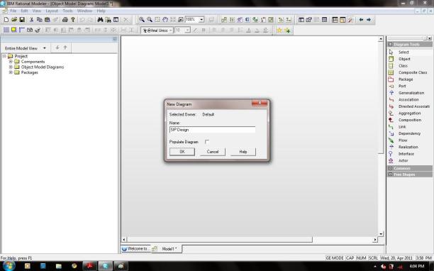
Fig.10.1: Creating a new User Case Diagram
10.1 Drawing the Functional Overview UCD
The following are the system requirements, including the actors, the major function points of the system, and the relationships between them, for this procedure:
- The actors that interact with the system are:
– Caller – The one who initiates a call.
– Callee – The one who receives a call request from caller.
- The system function points are:
– Call to be established between two subscriber via SIP Server.
– The SIP Server receives incoming and outgoing call requests and tracks users in Registrar.
- The actors interact with the system in the following ways:
– The Caller and Callee places and receives calls.
– The SIP Server checks the authentication in Registrar and establishes path for communication if authenticated.
10.1.1 Drawing a Boundary Box and Actors
The boundary box defines the system under design from the external actors. Use cases are inside the boundary box and actors are outside the boundary box. In this procedure, you draw a boundary box and actors, as shown in the following illustration.
To draw a boundary box and actors:
- Click the Create Boundary box icon in the Diagram Tools.
- Click in the upper, left corner of the drawing area and drag to the lower right. A boundary box called System Boundary Box is created.
- Rename the boundary box to SIP Protocol by typing “SIP Protocol” and pressing Enter.
- Click the Create Actor icon in the Diagram Tools.
- Click on the left side (outside) of the SIP Protocol boundary box. An actor with a name of actor_n, is created.
- Rename the actor to Caller by typing “Caller” and pressing Enter.
(Note: Do not include spaces in the names of the actors. Use an underscore instead.)
- Draw another actor called Callee on the right side of the SIP Protocol boundary box.
- In the Browser Window, expand the AnalysisPkg package and the Actors category to view the newly created actors.
10.1.2 Drawing the Use Cases
A Use Case represents a particular function of the system. In this procedure, we draw the following use cases, as shown in the following illustration:
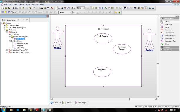
Fig.10.2: drawing the use cases
To draw the use cases:
- Click the Create Use Case icon in the Diagram Tools.
- Click in the boundary box. A use case with a default name of usecase_n is created.
- Rename the use case to Registrar by typing “Registrar” and pressing Enter.
- Repeat Steps 2 and 3 to create the following use cases:
- SIP Server
- Redirect Server
- In the Browser Window, expand the AnalysisPkg package and the Use Cases category to view the newly created use cases.
10.1.3 Entering a Use Case Description
In this procedure, we enter a description for each use case. To enter a use case description:
- In the Browser Window, expand the AnalysisPkg package and Use Cases category, right-click Registrar, and click Features. The Features dialog box appears.
- Click the Description tab and type the following text: “General function of the system is that it must be able to place a free call between registered user .” Click OK to apply the changes and to close the Features dialog box.
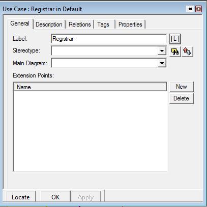
Fig10.3: entering a use case description
- Repeat Steps 1 through 3 for the rest of the use cases
- Click OK to apply the changes and to close the Features dialog box.
10.1.4 Associating Actors with Use Cases
The Caller actor places a calls request to SIP Server. SIP Server checks for authentication of both Caller and Callee.
To draw association lines:
- Click the Create Association icon in the Diagram Tools.
- Click the edge of the CALLER actor and then click the edge of the Registrar use case. An association line with the name label highlighted is created. Press Enter.
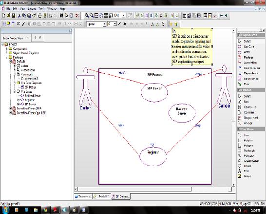
Fig.10.4: Associationg actors with use cases
- Repeat Steps 1 and 2 to create association lines between:
- The CALLER actor and the Registrar use case.
- The Callee actor and the Registrar use case.
- The Caller actor and the SIP Srever use case
- The Callee actor and the SIP Srever use case.
10.1.5 Drawing Generalizations
A Generalization is a relationship between a general element and a more specific element. The more specific element inherits the properties of the general element and is substitutable for the general element. A generalization lets us derive one use case from another. In this procedure, we draw generalizations indicating that SIP Server use case is derived from the Registrar use case and the Registrar use case, as shown in the following illustration.
To draw a generalization:
- Click the Create Generalization icon in the Diagram Tools.
- Click the SIP Server use case and draw a line to the Registrar use case.
- Click the Create Generalization icon in the Diagram Tools.
- Click the SIP Server use case and draw a line to the Registrar use case.
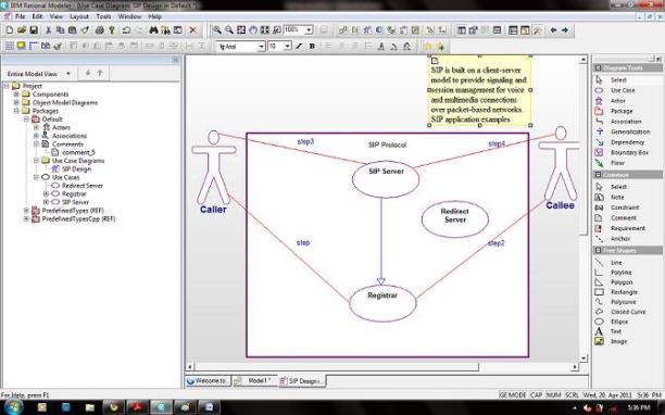
Fig.10.5: Drawing the generalizations
- In the Browser Window, expand the AnalysisPkg package, the Use Cases category, and then the SIP Serveruse case to view the newly created generalizations.
10.1.6 Adding Remarks to Model Elements and Diagrams
We can add remarks to specify additional information about a model element or diagram. In this procedure, we add a comment to the Functional Overview UCD, as shown in the following illustration.
To add a remark:
- Click the Comment icon in the Common Diagram Tools.
- Click in the top section of the diagram.
- Type the following text: “SIP is built on a client-server model to provide signaling and session management for voice and multimedia connections over packet-based networks.
SIP application examples include audio, video conferencing, instant messaging.”
- In the Browser Window, expand the AnalysisPkg package and the Comments category to view the newly added comment.
10.2 Creating the SIP Overview UCD
The SIP Overview UCD breaks down the SIP use case and identifies the different types of service that can be placed as use cases. In this exercise, we develop the SIP Overview UCD, as shown in the following illustration
To create the Registrar Overview UCD:
- In the Browser Window, expand AnalysisPkg package, right-click Use Case Diagrams, and then click Add New Use Diagram. The New Diagram dialog box appears.
- Type “SIP Design” and then click OK. Modeler automatically adds the SIP Overview UCD to Use Case Diagrams category in the Browser Window.
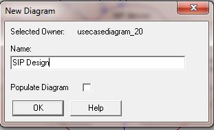
Fig.10.6: creating an user case description
10.2.1 Entering a Use Case Description
In this procedure, we enter a description for each use case. To enter a use case description:
- In the Browser Window, expand the AnalysisPkg package and Use Cases category, right-click SIP, and click Features. The Features dialog box appears.
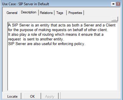
Fig.10.7 entering the user case description
Click the Description tab and type the following text: “A SIP Server is an entity that acts as both a Server and a Client for the purpose of making requests on behalf of other client.
It also play a role of routing which means it ensure that a request is sent to another entity.SIP Server are also useful for enforcing policy. ”
- Click OK to apply the changes and to close the Features dialog box. Repeat Steps 1 through 3 for the Registrar use cases. Type the following text: “A Registrar is a server thats accepts Register request from Caller and Callee. It stores the information of Caller and Callee which is then provided to SIP Server.”
- Click OK to apply the changes and to close the Features dialog box.
10.2.2 Drawing Generalizations
In this procedure, we draw generalizations to show that the SIP Serer and the Redirect Server use cases derive from the Registrar, as shown in the following illustration.
To draw a generalization:
- Click the Create Generalization icon in the Diagram Tools.
- Click the SIP Server use case and draw a line to the Registrar use case.
- Click the Create Generalization icon in the Diagram Tools.
- Click the Redirect Server use case and draw a line to the Registrar use case.
10.2.3 Adding Requirement Elements
Adding Requirement Elements to the Model We can represent requirements in the browser window and diagrams as requirement elements. Requirement elements are textual annotations that describe the intent of the element.
In this procedure, we add the handset model requirements to the RequirementsPkg package in the Browser Window, as shown in the following illustration.
To add requirements elements:
- In the Browser Window, right-click the RequirementsPkg package, click Add New, and then click Requirement. A requirement with a default name of requirement_n is created.
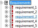
Fig.10.8: adding the requirement elements
- Rename the use case to requirement_n by typing “requirement_1” and pressing Enter.
- Right-click requirement_1and then click Features. The Features dialog box appears.
Click the Description tab and type the following text: “The Caller and Callee shall register themself in Registrar before a place call sequence begins..”
Click OK to apply the changes and to close the Features dialog box.
- Repeat Steps 1 through 5 to create the following requirements and descriptions:
- requirement_2- “When a call is being initiated SIP Server will check the authentication of Caller and Callee in Registrar.”
- requirement_3- “After authentication the Caller and Callee would able to make call, text messsage via SIP Server.”
- requirement_4- “The call shall be of maximum 40 minutes while the text message can be upto 300 character.”
- requirement_5- “A Caller can make 12 calls per day and can send 50 text message in a month.”
- In the Browser Window, expand the RequirementsPkg and the Requirements category to view the newly created requirements elements.
10.2.4 Adding Requirement Elements to a Diagram
In this procedure, we add requirement elements to the Registrar Overview UCD to show the requirements trace to the use cases.
To add the requirement elements to the Registrar Overview UCD:
- In the Browser Window, expand the RequirementsPkg package and the Requirements
- Click requirement_1 and drag it to the right of the Registrar use case.
- Select requirement_2 and drag it to the lower left of the SIP Server use case.
- Select requirement_3 and drag it to the lower right of the SIP Server use case.
Setting the Display Option to Show the Requirement the Element Name
In this procedure, we set the display option to show the requirement the names of the elements, as shown in the following illustration.
To set the display option to show the requirement element name:
- Right-click requirement_1 in the diagram and click Display Options. The Requirement Display Options dialog box appears
- Under Show, click Name to display the name of the requirement.
- Click OK.
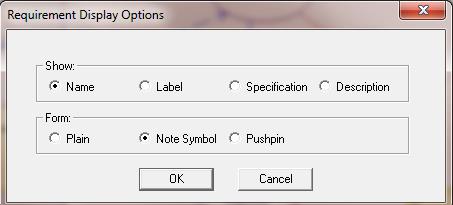
Fig:10.9: adding the requirement cases
- Repeat Steps 1 through 3 for requirement_2 and requirement_5 to Name
10.2.5 Drawing Dependencies
A dependency is a direct relationship in which the function of an element requires the presence of and may change another element. We can show the relationship between requirements, and between requirements and model elements using dependencies. In this procedure, we can draw dependencies between the requirement elements and the use cases, as shown in the following illustration…
To draw dependencies:
- Click the Dependency icon in the Diagram Tools.
- Click the requirement_1 requirement and draw a line to the Registrar use case.
- Click the requirement_2 requirement and draw a line to the SIP Server use case.
- Click the requirement_3 requirement and draw a line to the SIP Server use case.
- Click the requirement_4 requirement and draw a line to SIP Server use case.
- Click the requirement_5 requirement and draw a line to SIP Server use case
- In the Browser Window, expand the RequirementsPkg package and the Requirements category to view the dependency relationships.
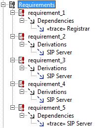
Fig.10.10: adding the requirement dependencies
10.2.6 Defining the Stereotype of a Dependency
We can specify the ways in which requirements relate to other requirements and model elements using stereotypes. A stereotype is a modeling element that extends the semantics of the UML metamodel by typing UML entities. Modeler includes predefined stereotypes and we can define ourr own stereotypes. Stereotypes are enclosed in guillemets on diagrams, for example, «derive». In this procedure, we set the following types of dependency stereotypes, as shown in the following illustration:
- Derive – A requirement is a consequence of another requirement.
- Trace – A requirement traces to an element that realizes it.
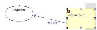
Fig: 10.11: defining the stereotype
To define the stereotype of a dependency:
- Double-click the dependency between requirement_1 and Registrar. The Features dialog box appears.
- In the Stereotype list, select the trace in PredefinedTypes check box.
- Click OK to apply the changes and to close the Features dialog box.
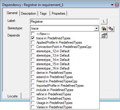
Fig: 10.12: defining the stereotype of a dependency
- Repeat Steps 1 through 3 for:
- The dependency between requirement_2 and SIP Server– Set to drive in PredefinedTypes.
- The dependency between requirement_3 and requirement_4 SIP Server – Set to drive in PredefinedTypes
- The dependency between requirement_5 and SIP Server – Set to trace in PredefinedTypes.
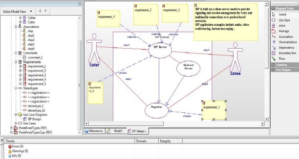
Fig.10.13: final model
10.3 Summary of the model
In this module, we created UCDs that show the functions and requirements of the wireless telephone and placing a call. We became familiar with the parts of a UCD and created the following:
- System boundary box
- Actors
- Use cases
- Association lines
- Dependencies
- Generalizations
- Requirements
SIP Pros & Cons
Pros:
- SIP works independently of the type of session, or the media used, giving it flexibility.
- It is an open standard, allowing multivendor support and integration. Applications can be written to customize SIP uses.
- SIP messages are clear text, making troubleshooting easier.
- SIP can accommodate multiple users with differing capabilities. For instance, in a conference that has some users with video capability and some only with audio capability, the video users can see each other. They do not have to drop down to audio only, as with other protocols.
- SIP re-uses several existing and mature internet services and protocols such as DNS, RTP, RSVP etc. No new services have to be introduced to support the SIP infrastructure, as much of it is already in place or available off the shelf.
Cons:
- Processing text messages puts a higher load on gateways. The router must translate that text into a language that the router can understand. Code for this must be in the Cisco IOS.
- SIP is a fairly new protocol, so fewer people understand it than the older protocols. One must have trained support personnel if we intend to implement SIP within our Callee.
- When we are using both SIP and SCCP phones on the same Callee, we must convert between in-band and out-of-band DTMF tones.
- SIP features are still being developed, and many vendors have proprietary implementations of the protocol.
Conclusion:
This paper introduces SIP clients & servers, User agents, Proxy server, Redirect servers & Registrars. Message Request & Responses. Different call flow & call scenario are also discussed.
SIP is promising because it is a simple, open protocol that can be deployed in carrier and enterprise networks and because it enables new multimedia applications in voice, data, and video. For service providers, H.323 is a legacy technology that will eventually give way to SIP because of the inherent simplicity of SIP and potential for new media-blending services (Internet telephony). However, in the enterprise market, H.323 has gained significant support because of its manageability, reliability, and interoperability with the PSTN and will continue to do so for some time. Most serious implementers of SIP are considering a SIP-to-H.323 inter-working function / gateway as an essential element of any network.
There is a general consensus among standards organizations, companies, and technology experts that standardized procedures need to be specified to allow seamless inter-working between the two protocols. Bodies such as TIPHON (ETSI), IMTC, and IETF are working to address this topic.
References: